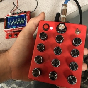
Tri-Oscillator Noise Box Synth
I designed and built this synth as (hopefully) the first in a line of similar-style modules. It has three oscillators with a few quirky modulations that altogether produce range of weird sounds. It can make multi-note drones as well as some rough, rhythmic wubs and also even some FM (frequency modulation) sounds if you patch together the 1st and 3rd oscillator.
In this post I’ll go over some of the functions and the inner workings of this synth. To hear a demo, check out this video:
Basic Functions
Before getting into the details of how everything works on the inside, let’s take a quick look at some of the controls:
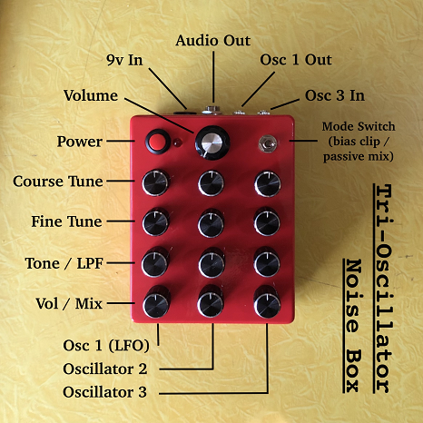
You can see that there are three columns of knobs, one for each oscillator. For each oscillator, you can control the pitch via the course- and fine-tune knobs. You also have the ability to (crudely) shape the wave by cutting some high frequencies with the LPF (low pass filter) knobs. And finally, the “Vol / Mix” knob allows you to mix that wave with the other two.
Weird Accidental Function #1 – Bias Clipping Mode
The “Mode” switch is where things get a little more interesting (in my nerdy opinion). This selects between 1) a standard passive mix of all three waves and 2) an amplified signal that clips off the high frequencies from the bottom half of the wave. I discovered this by total accident when I tried mixing the signals through an op-amp and ended up making some unexpected sounds. I ended up liking the result so much that I kept it in the final design. To visualize the two different modes, take a look at the following waves (viewed through a tiny digital oscilloscope):
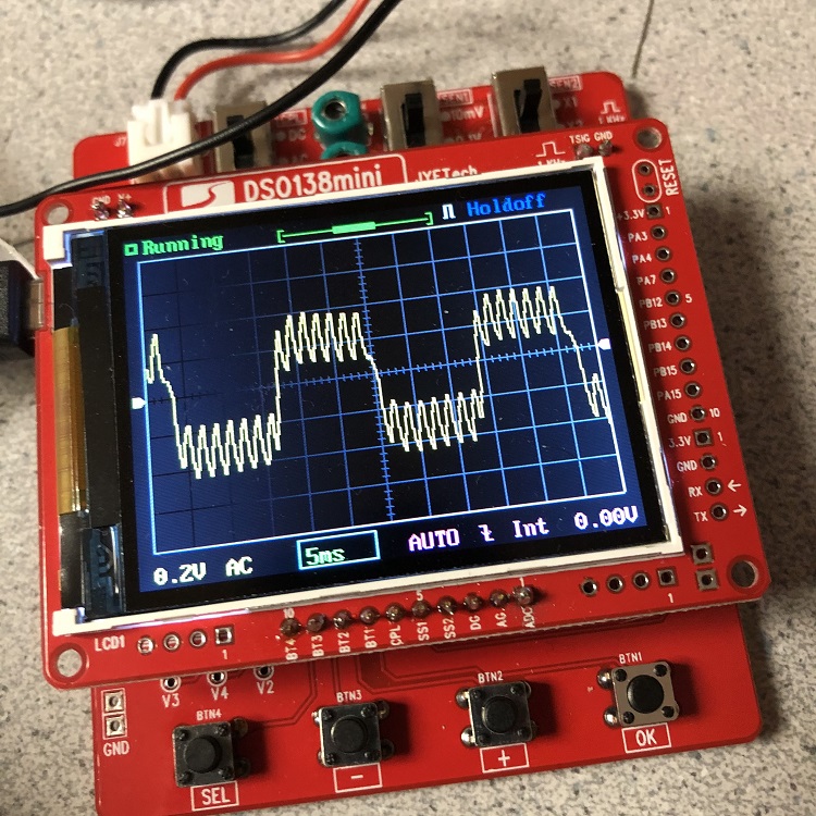
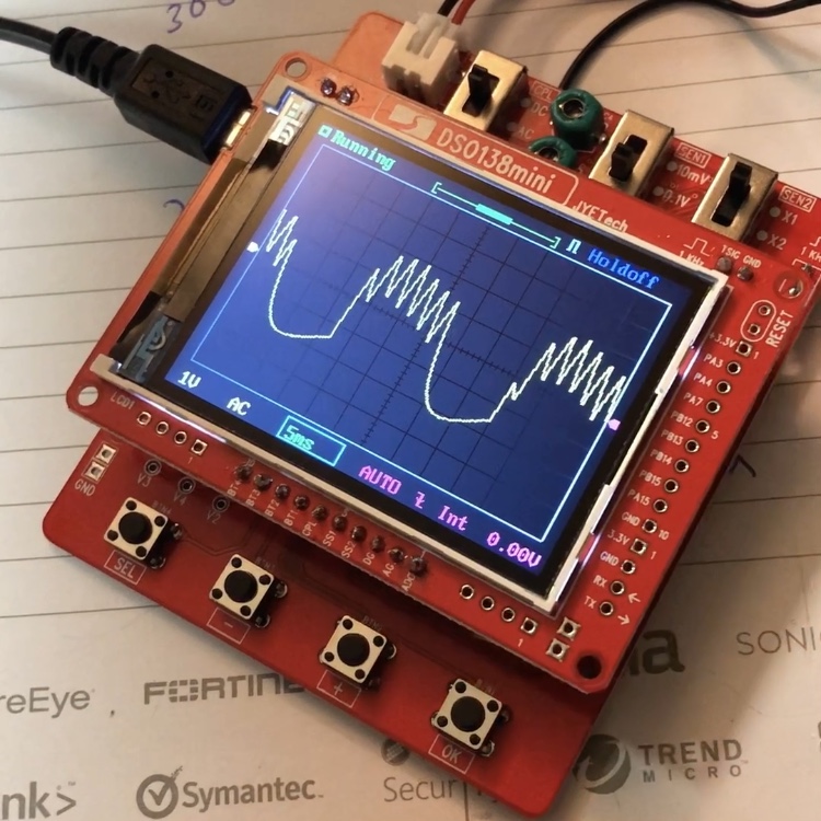
You can see in the second image, the bottom half of the wider waveform is missing the higher-frequency wave. This creates some very interesting rhythmic effects when one of the waves is slowed down below an audible pitch range. As you slow down the wave you start to hear the silence in those lower swings of the slower waveform.
I’d like to point out that I am by no means an electrical engineer and all of what I’ve described is pretty much solely based on my direct observations and experimenting with this circuit. So in terms of the actual physics that is happening here, unfortunately I can’t provide a fully-educated explanation. My (uneducated) opinion is that the op-amp is unevenly biased, causing only the bottom half of the wave to be clipped.
Weird Accidental Function #2 – FM Synthesis
The second thing I discovered by accident was the ability to create FM (or “Frequency Modulation”) synthesis by modulating one wave with another.
This originally started out as me simply trying to make this synth “modular” by adding some 3.5mm input and output jacks. First I wanted to be able to control the pitch of one of the oscillators with an external source like a sequencer, so I added a CV (control voltage) input for oscillator #3. Then after playing with the circuit on the breadboard, I realized that it would be pretty cool if I expanded the range on oscillator #1 so that it could get down into single-digit Hz ranges. This allowed me to make some slower rhythms in the “bias clipping” mode that I thought sounded nice. It was then I realized that this was sort of a crude LFO (low-frequency oscillator), and therefore it deserved it’s own output.
So at this point, I had two 3.5mm jacks, one input and one output. The clear question at this point was “I wonder what would happen if I patched these two together??”.
Lo and behold, I was greeted with some pretty crazy laser beam sounds that I found out later were the makings of some crude FM synthesis.
What’s Inside?
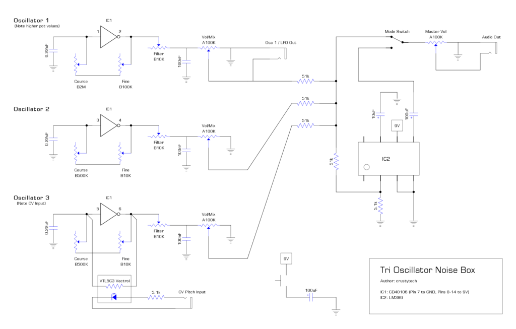
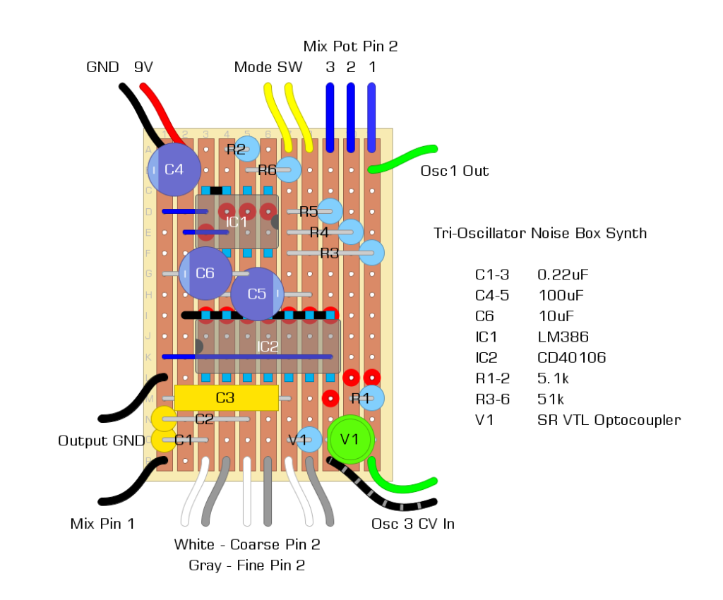
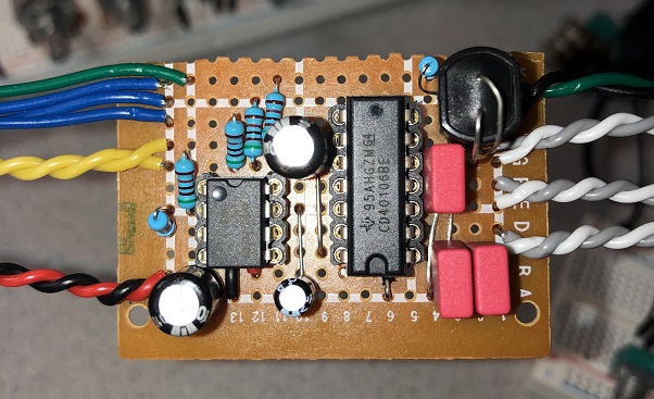
All considered, this is actually a really simple circuit. I would say about half of the components are all the damn potentiometers. The three oscillators are all produced by a single CD40106 hex inverter chip. There is a passive summing section that adds the three signals together and there is a LM386 op-amp that amplifies the summed signal. That’s pretty much it. Most everything else happens off-board (aka pots, jacks, switches, etc.). Here is a stripboard layout detailing the onboard circuit elements:
…And here is the completed circuit board:
Below is a picture of the completed off-board wiring. Here are the values for the potentiometers:
- Course Tune: B500K
- Fine Tune: B10K
- Tone/LPF: B10K
- Volume/Mix: A100K
The pictured ceramic capacitors are each 100nF. Note here that the capacitors paired with the 10K potentiometers create a simple passive low-pass filter.
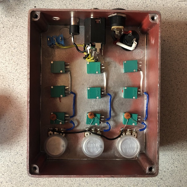
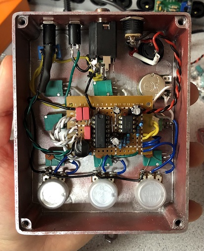
Here’s an image of the guts of the completed synth with everything connected (I’m aware that it’s a bit of a rat’s nest…). Note that I did end up replacing the tuning pots for oscillator 1 with larger-value pots. This was after I realized I wanted Oscillator 1 to get significantly slower than the rest. They are 2M and 100K, respectively.
Closing Thoughts
This was an exploratory experience for me. If I went back and did it again, I definitely have a few key things that I would improve. One of those being jack positioning and just cleaning up the build layout in general, as I ended up having to squeeze a few components. In terms of the circuit itself, I would probably change the “passive mix” mode to a proper “active” mix as there is a bit of noticeable volume loss in that mode. I’ll mention again that I’m by no means an electrical engineer so my circuit design “process” is almost completely based on “let me try this and see if it works” vs actually knowing theory and calculating the “correct” values.
Otherwise I’m actually really happy with this build! I genuinely enjoy playing with this synth and I’m surprised at the range of sounds that it can produce being such a small circuit.
Additional Resources
Circuit diagram / schematic:
